What Is Plasma?
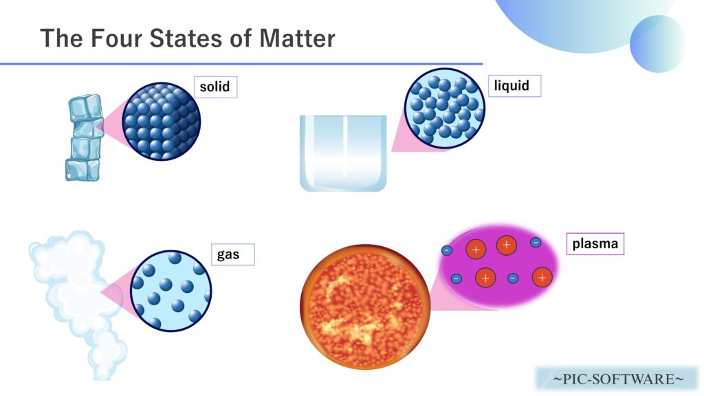
Figure 1: Four States of Matter
Matter is commonly classified into solids, liquids, and gases, but by heating a gas further, it is possible to generate plasma.
For this reason, plasma is often referred to as the “fourth state of matter.”


In this article, we will analyze an industrial plasma etching system using PIC-PLASMA 3D (plasma analysis software).
A plasma etching system is a device that removes material from a surface by using active species and ions in plasma. In semiconductor manufacturing, it is widely used for microfabrication of silicon, insulating films, and metal films.
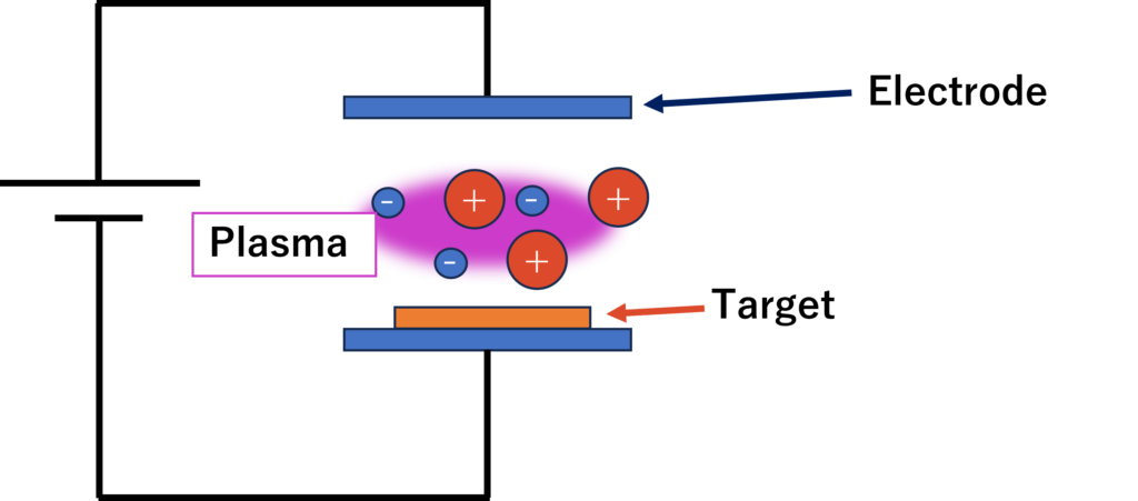
Figure 2: Conceptual Diagram of Plasma Etching
The basic principle is as follows:
- A reactive gas is introduced into a vacuum chamber, and high-frequency power is applied.
- The gas is discharged to generate plasma.
- The target material is removed through a combination of chemical action and physical action.
Chemical action occurs when radicals generated in the plasma react with the surface of the material being processed, producing volatile by-products. For example, when fluorine radicals react with silicon, the reaction forms products that can be easily exhausted as gas, thereby removing the surface material.
Physical action occurs when positive ions in the plasma are accelerated toward the substrate by the electric field and collide with the surface. This ion bombardment can sputter surface atoms and enhance the chemical reactions. As a result, anisotropic etching can be achieved, allowing material to be etched mainly in the vertical direction.
Inside the system, applying high-frequency power to the electrode holding the substrate creates a self-bias voltage, which helps ions strike the substrate almost vertically. This makes it possible to process fine patterns deeply and accurately without widening them laterally.
The features of plasma etching systems include:
- Suitable for fine processing
- Capable of anisotropic processing
- Selectable material-specific etching behavior by choosing the reaction gas
These are the main advantages.
On the other hand, challenges include:
- Substrate damage caused by excessive ion bombardment
- Mask wear
- Redeposition of reaction by-products
These are typical issues.
In short, a plasma etching system is a device that precisely removes material from a surface by utilizing the chemical reactivity of plasma generated in a vacuum and ion bombardment.
Load Analysis on the Target in a Plasma Etching System
Let us perform a collision simulation of plasma striking the target inside a plasma etching system using PIC PLASMA 3D.
The analysis model is shown below.
Analysis Model
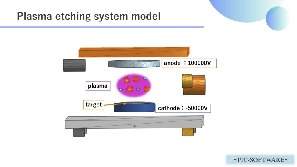
Figure 3: Analysis Model of the Plasma Etching System
A plasma etching system model like the one above was created, and trajectory analysis of the plasma inside the chamber was carried out.
The plasma generation mechanism is shown below.
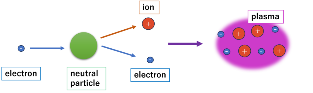
Figure 4: Plasma Generation Process
Analysis Conditions
The analysis conditions are as follows.
| Analysis Software | PIC-PLASMA 3D |
| Analysis Type | Plasma Analysis |
| Analysis Object | plasma_etcher.step |
|---|---|
| Plasma Particle Species | Ar |
| Plasma Density | 1.0×10⁷ [particles/m3] |
| Cumulative Energy Target Object | input004 |
| Voltage | Cathode Voltage: -50000 [V] Anode Voltage: 100000 [V] |
| Time Step | 5.0×10⁻¹⁰ [s] |
| Total Simulation Time | 1.0×10⁻⁶ [s] |
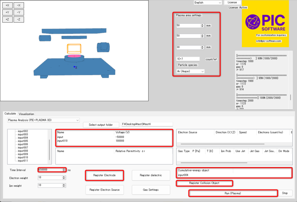
Figure 5: Setting Analysis Conditions in PIC-PLASMA 3D
Analysis Results
Figure 6: Plasma Analysis Results Inside the Plasma Etching System
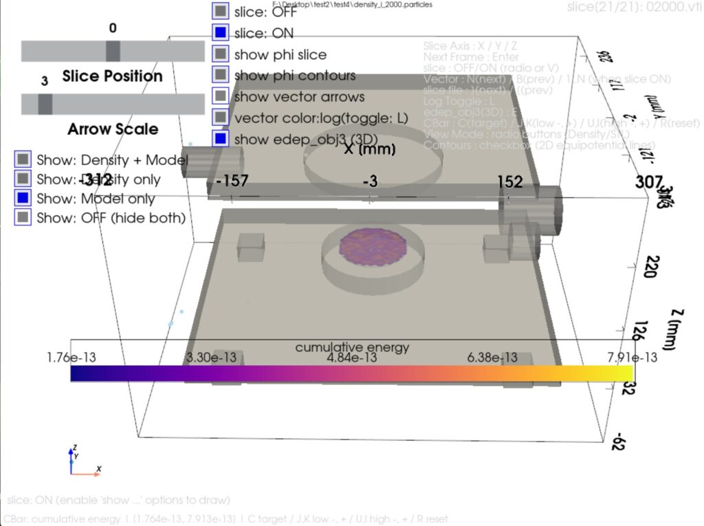
Figure 7: Cumulative Collision Energy of the Target Plasma
The material shown above is an actual analysis result calculated using PIC-PLASMA 3D.
Figure 6 visualizes the behavior of ions (Ar+) in the plasma as an animation.
Figure 7 shows the cumulative collision energy (kinetic energy) between the target and the plasma.
Please note that the CAD model used here was created as a simplified model, so the electrode voltage and other conditions are also simplified.
In addition, PIC-PLASMA 3D can output various kinds of data in addition to the calculation results shown above.
- Electron density
- Current density vectors
- Electric field vectors
- Velocity vectors
- Collisions with plasma in background gas and jet gas
*The above is just one example. Please make full use of PIC-PLASMA 3D for the development of plasma-related products.