lite Edition Operation Manual
Using CAD files for a magnetron sputtering(magnetron_sputtering.step) device as an example, we will set the analysis conditions in this software.
1 How to create 3D CAD files for analysis
1.1 FreeCAD settings and export procedure
This chapter explains how to export object files used in the analysis software “PIC-PLASMA 3D” using FreeCAD.
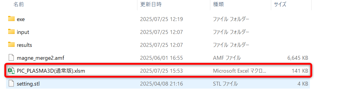
With PIC-PLASMA 3D, you need to export object files created with CAD in uncompressed AMF format. If you try to import files in formats other than AMF, an error may occur in the software.
Therefore, if your CAD software does not support exporting to AMF format, you will need to import the file into FreeCAD and convert it to AMF format before use.
1.2 How to install FreeCAD
-
- Go to the FreeCAD download page.(https://wiki.freecad.org/Download/ja)
- Install using the Windows 64-bit installer.
1.3 Starting and configuring FreeCAD
You need to change the mesh format of the objects to be simulated.
-
- Start FreeCAD.
- Select “Model > Object File.”
- Select “Edit > Settings” from the toolbar.
- Select “Import/Export > Mesh Format.”
- Uncheck “Export AMF files using compression” in Export.
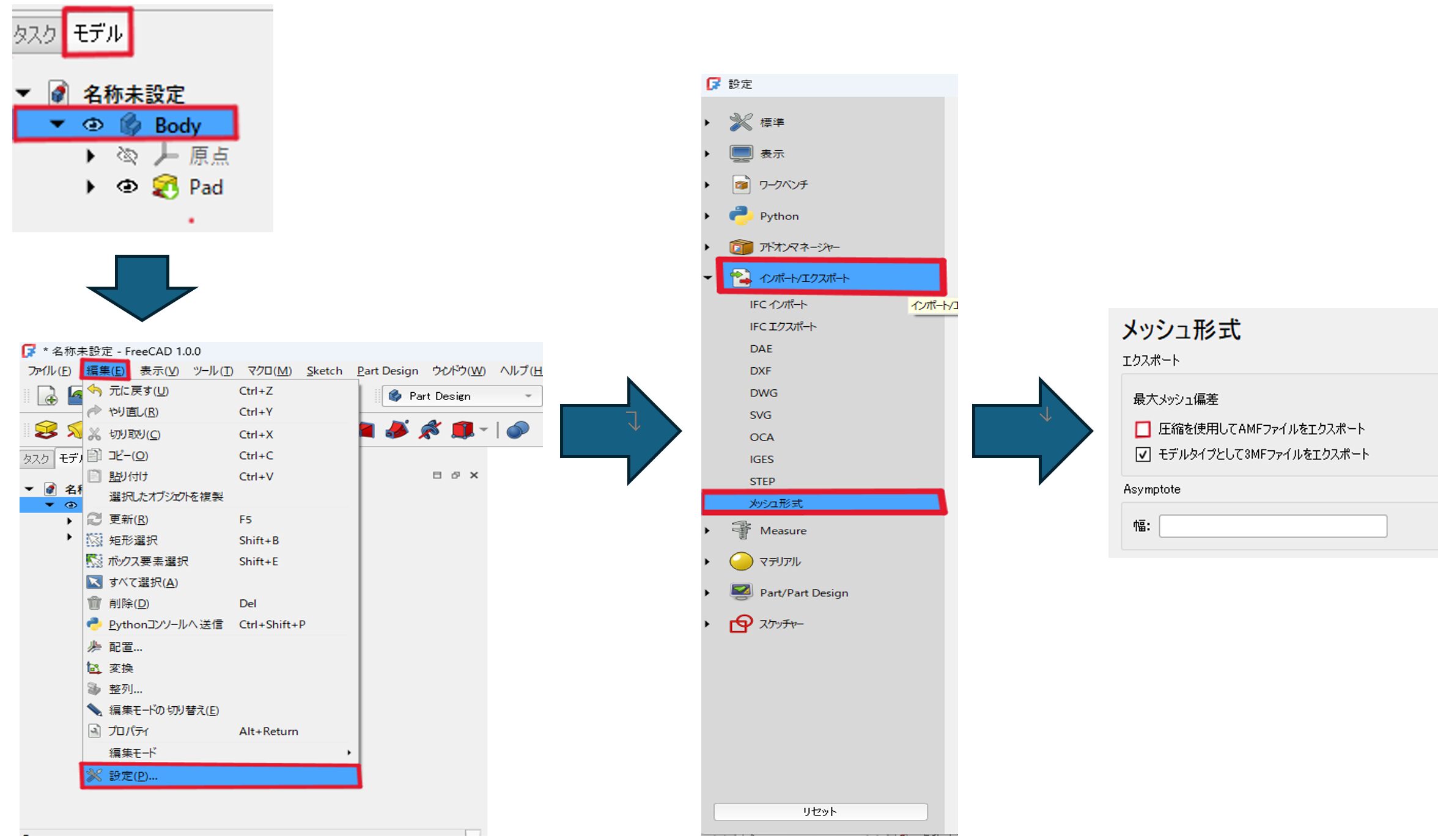
Important points
If there is no “Mesh Format” item, follow the steps below.
- Select Toolbar > File > Open.
- Open “setting.stl” in the PIC-PLASMA3D download folder.
- A blank file with no name will open.
- In state 3, follow the steps in 『Starting and configuring FreeCAD』.
1.4 How to export object files
-
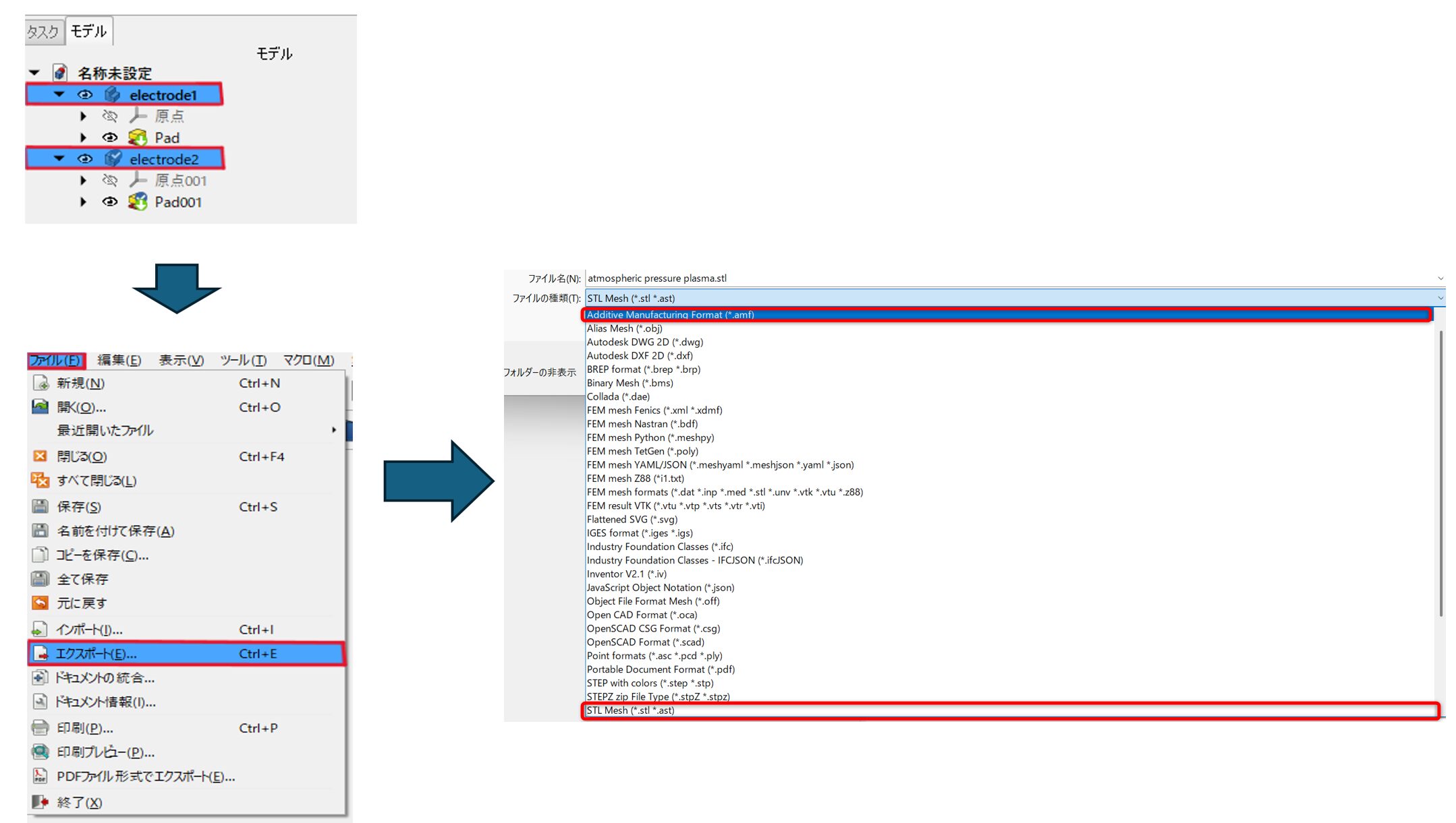
- Open the intermediate CAD file you want to analyze (STEP files are recommended) in FreeCAD.
- Select the object file to be analyzed. (If there are multiple objects, select them all.)
- Select Toolbar > File > Export.
- Set the file type to “Additive Manufacturing Format (*.amf)”.
Please use alphanumeric characters for file names.
Also, since the post-processing requires the “STL Mesh (*.stl *.ast)” format, let's export it here as well.
2 Analysis
①Start PIC-PLASMA3D.
②Open the Calculate sheet.
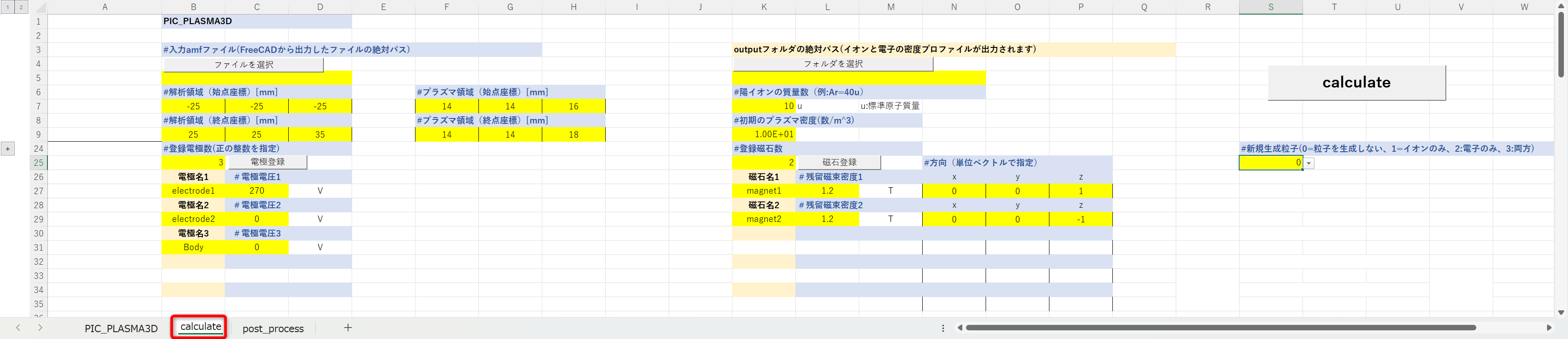
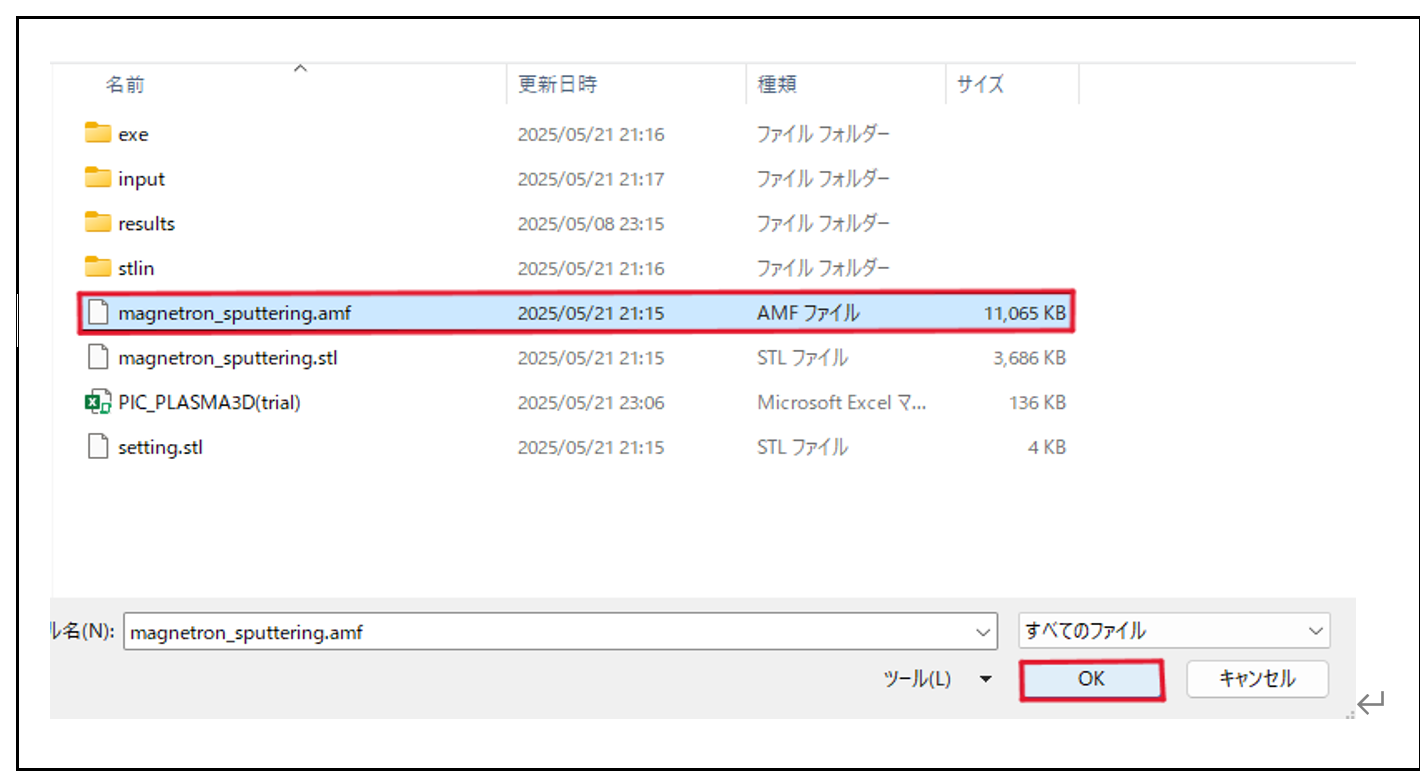
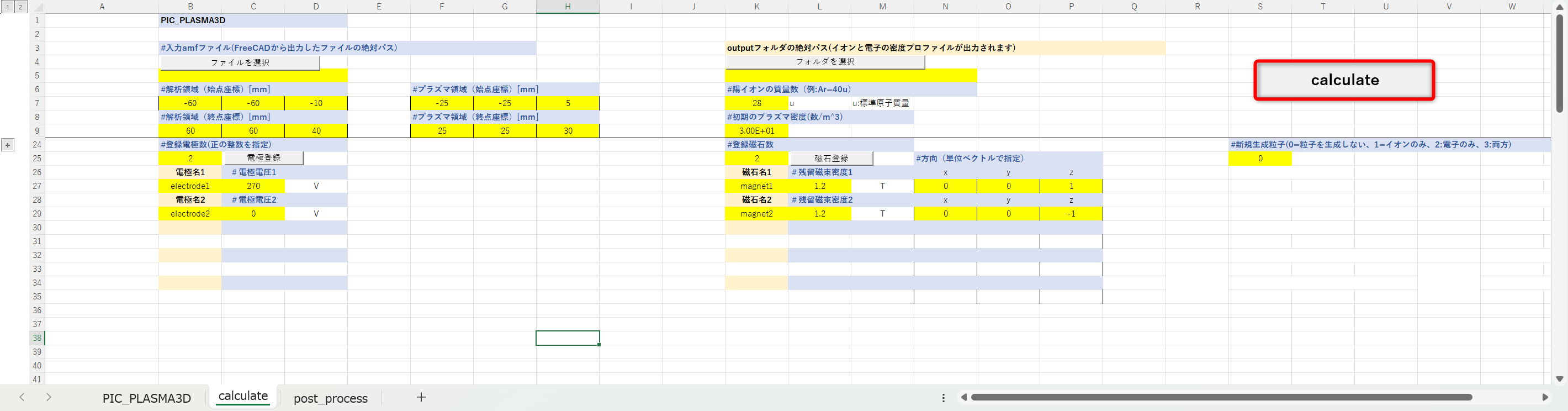
③ Select the input amf file > Select file.
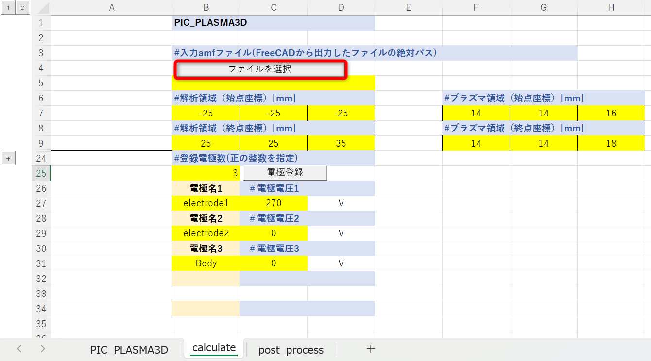
④Select the CAD file (e.g., magnetron_sputtering.amf) and press the OK button.
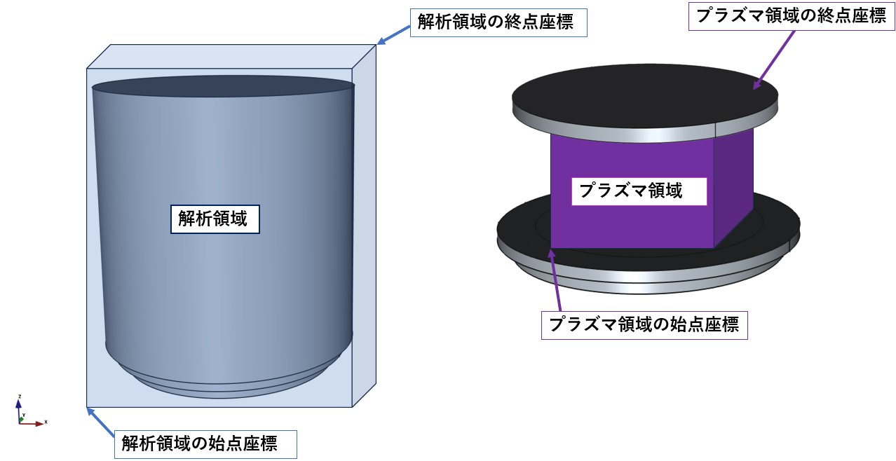
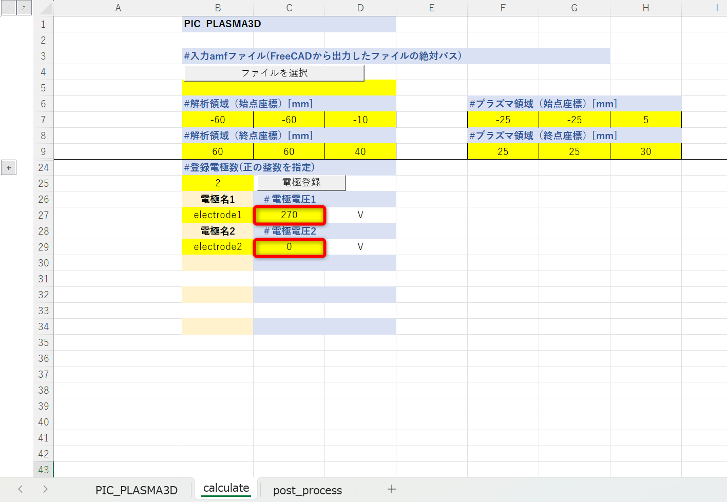
⑤Set the analysis domain and plasma domain.
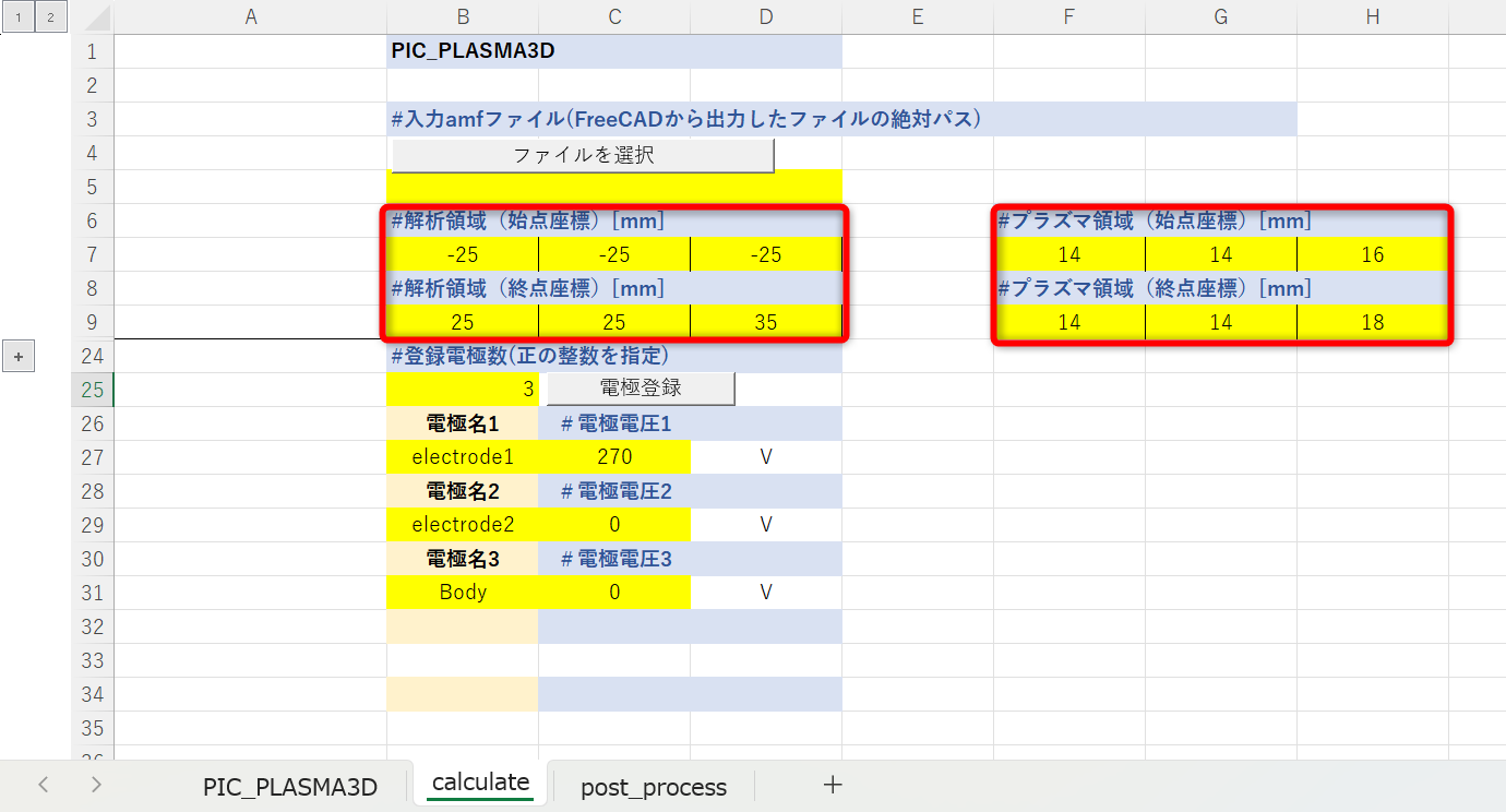
- In the analysis domain, specify the calculation domain containing objects (electrodes and magnets). (It is OK to be somewhat approximate.)
- In the plasma region, the user specifies the range of plasma to be placed. (The generation of ion beams and electron beams will be described later.)
The starting and ending coordinates of the calculation domain and plasma domain in magnetron sputtering are shown below.
Please refer to the following for information on how to display coordinates in FreeCAD.
⑥Specify the density [pcs/m3] of the plasma (ions・electrons) to be placed.
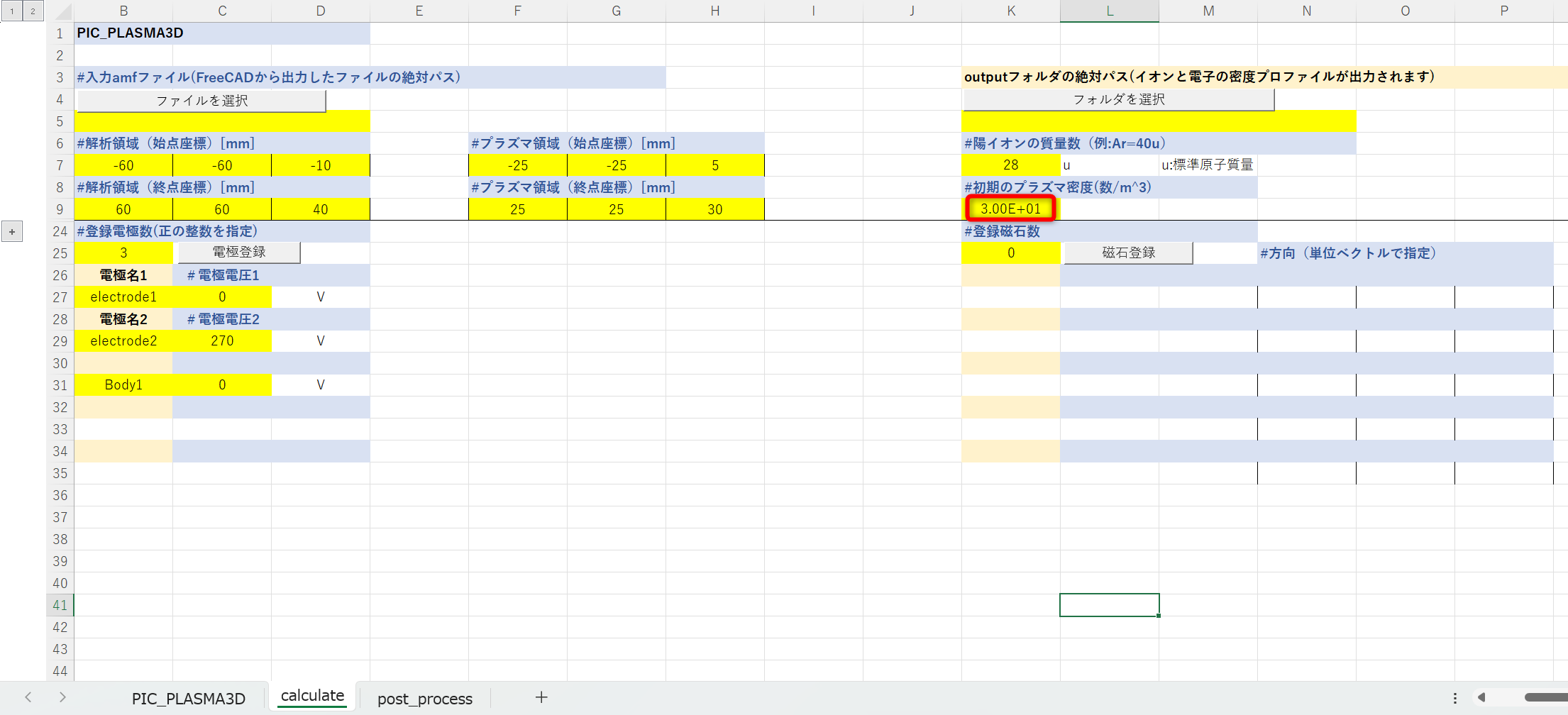
⑦Select the absolute path of the output folder > Select folder.
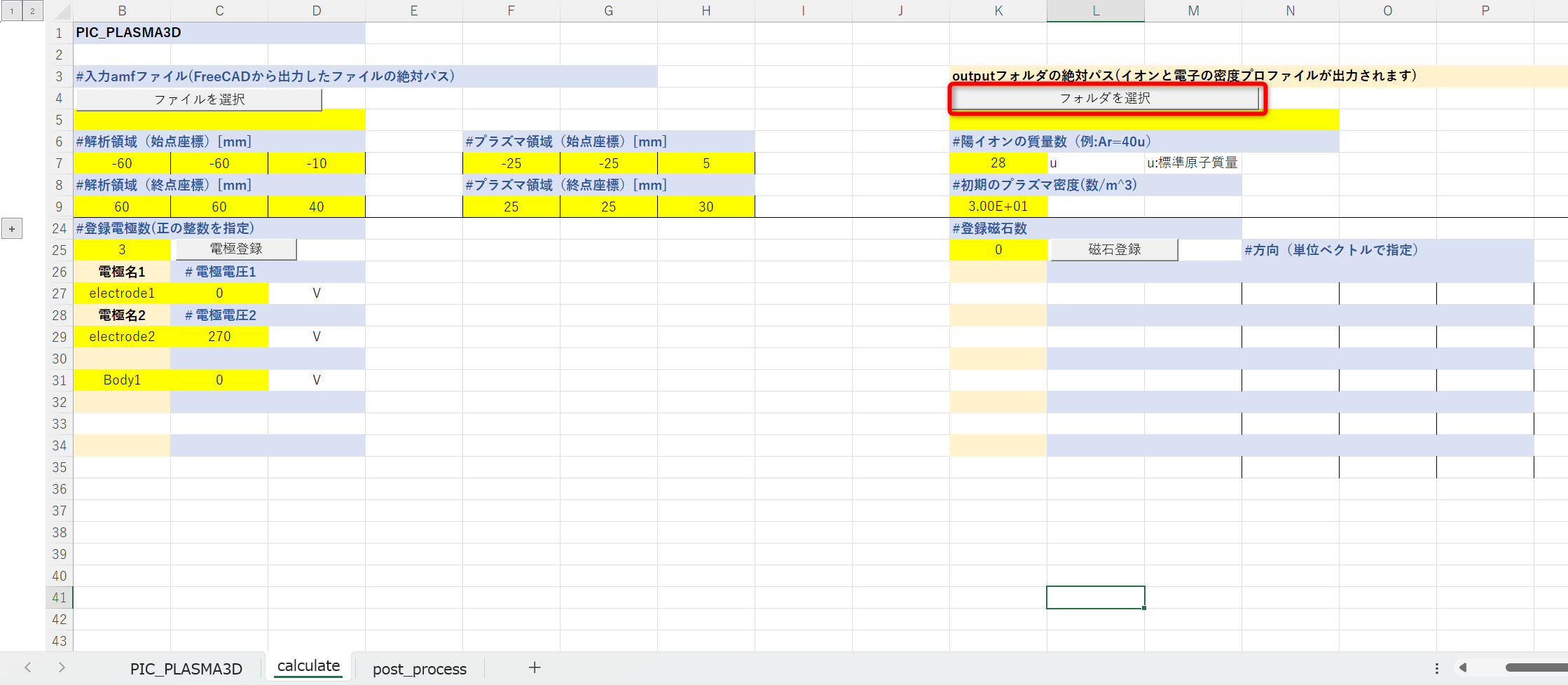
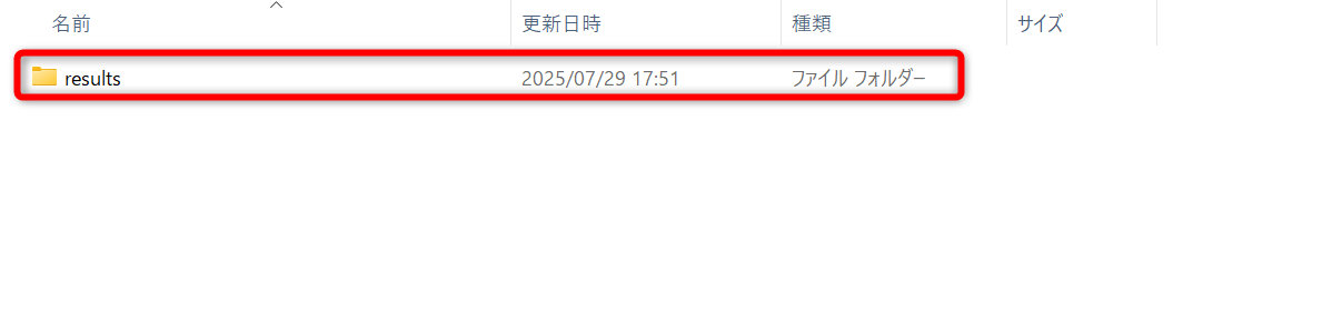
⑧Select the folder (optional) where you want to output the calculation results file.
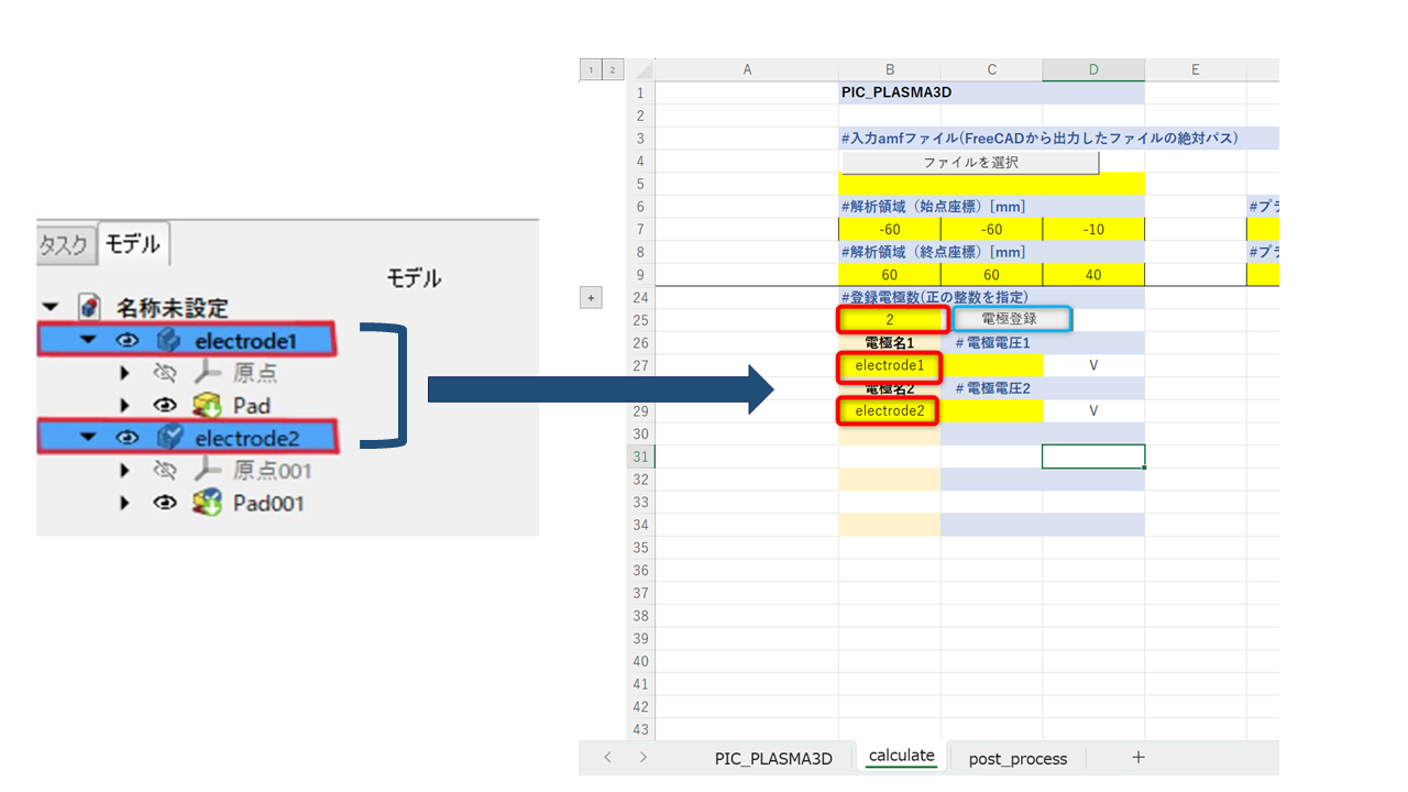
⑨Enter the number of electrodes exported in 1.4, left-click on “Register Electrodes” > Enter the electrode names in the Excel file. (Bodies that are not entered will be treated as vacuum areas.)
⓾Enter the electrode voltage (set arbitrarily by the user).
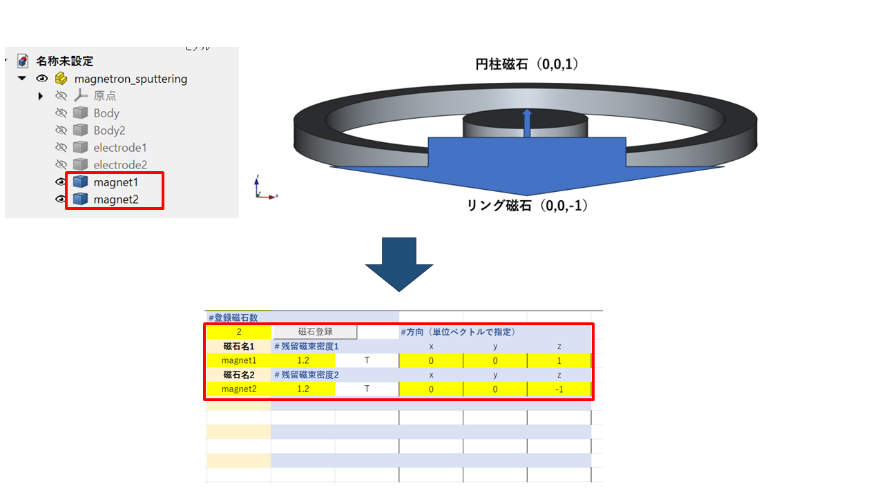
⑪When performing analysis that includes magnets, register the magnets in the same way as electrodes.
Please specify the direction from the S pole to the N pole of each magnet as a unit vector.
⑫If no new particles are generated, the input of analysis conditions is complete.
When you select the Calculate button, the command prompt will launch and automatically begin preparing for calculation.
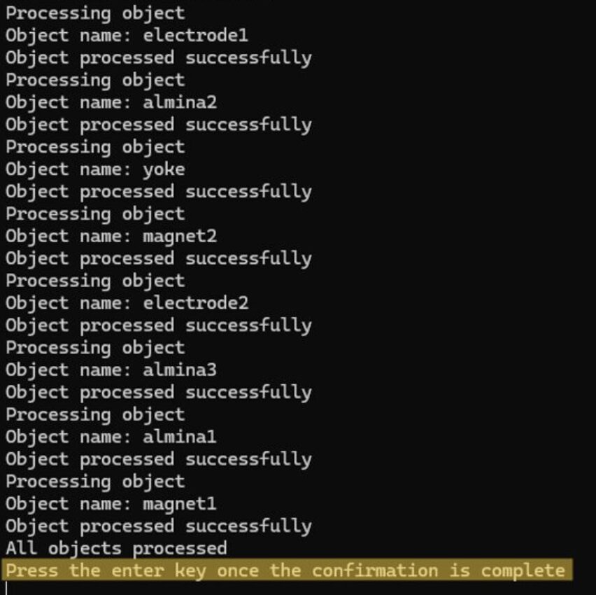
⑬After the command prompt starts up, wait a moment until the message “press the enter key once the confirmation is complete” appears, then press the ENTER key once. The calculation process will start, so wait until the command prompt closes automatically.
During calculation, the following screen will be displayed.
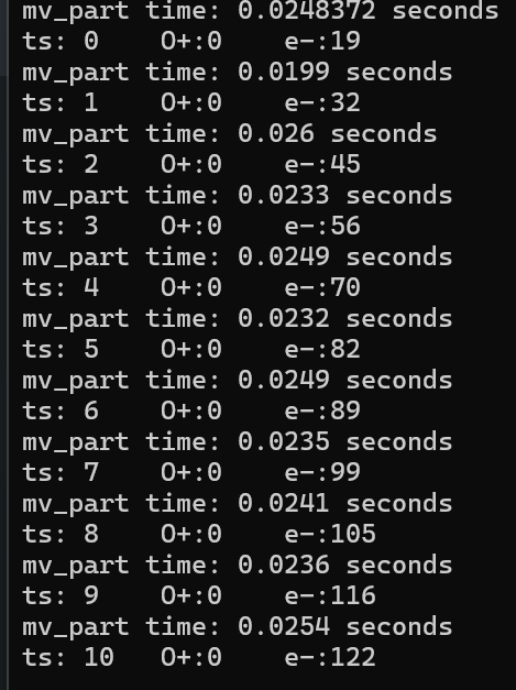
The meanings of each item are shown below.
-
- mv_part time: Calculation time per hour step
- ts: Number of time steps
- O+: Number of virtual particles (ions)
- e-: Number of virtual particles (electrons)

3 Visualization and explanation of calculation results
①Go to the post_process sheet.
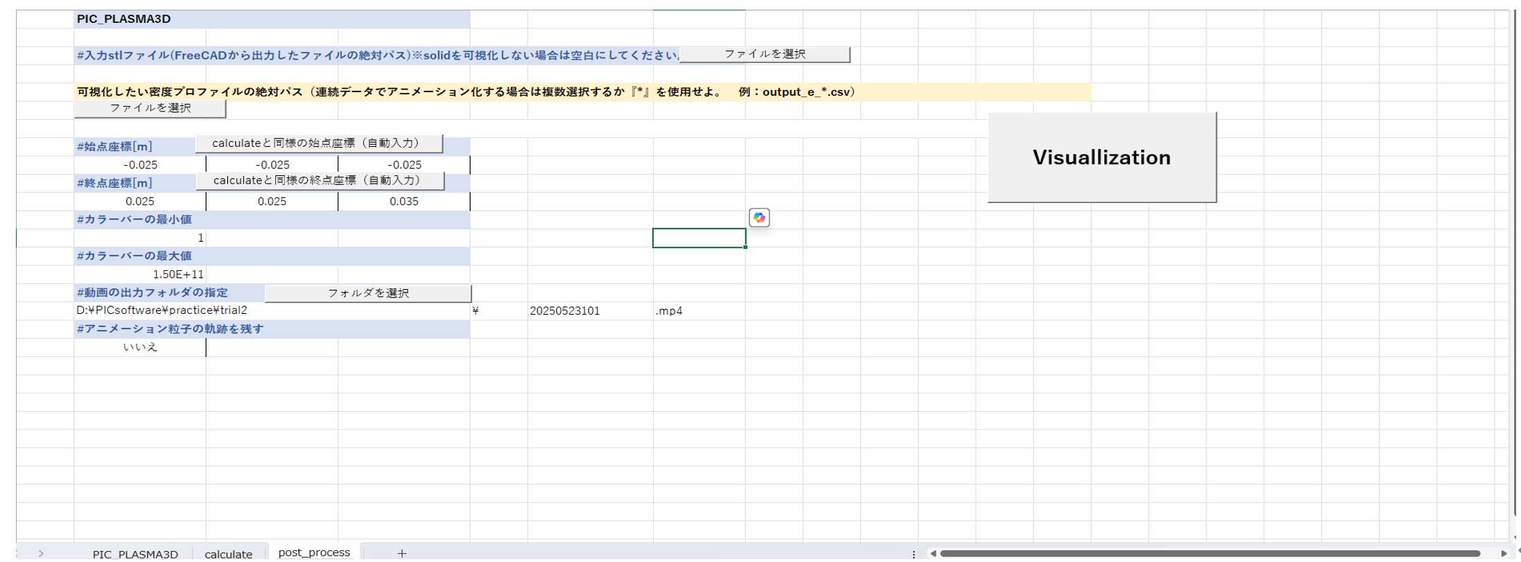
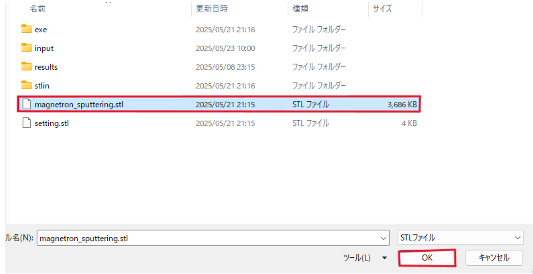
②When displaying solids (such as device structures) in 3D (not required), select Input stl file > Select file.
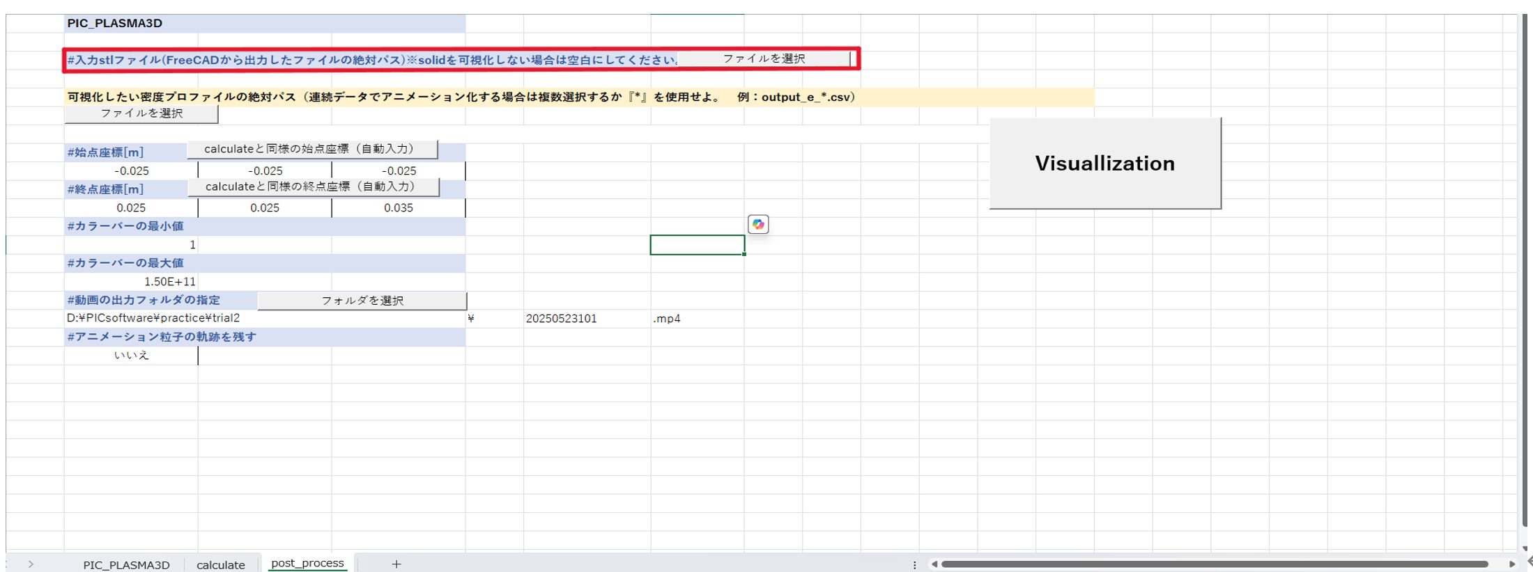
③Select the stl file output in 1.4 and press the OK button.
④Select the absolute path of the density profile you want to visualize > Select file.
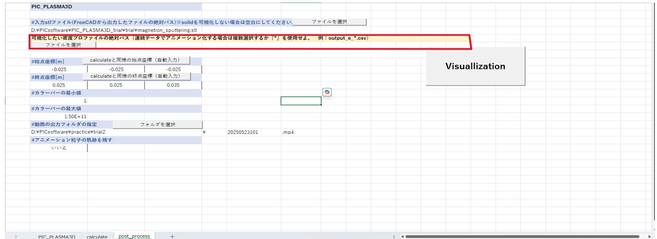
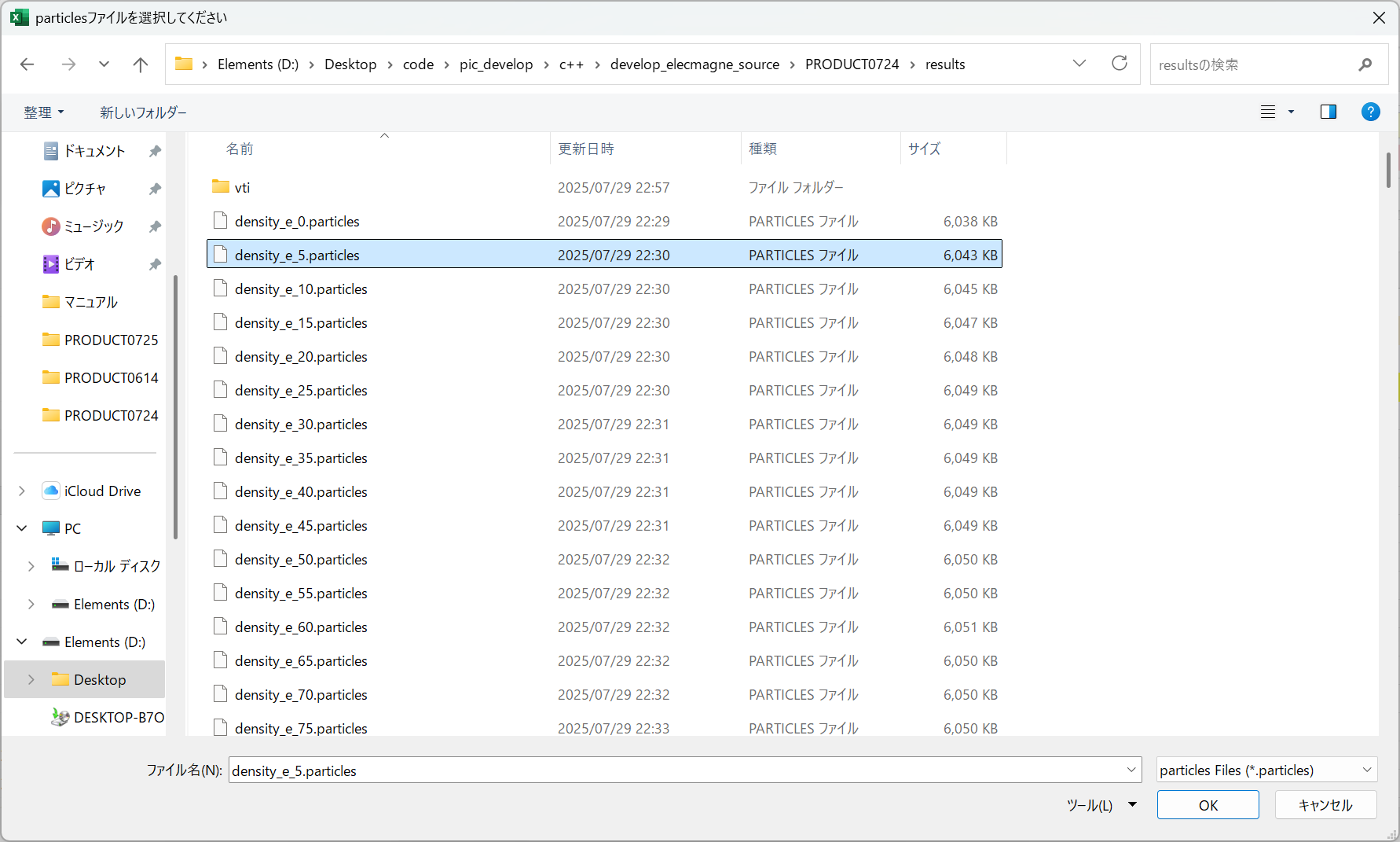
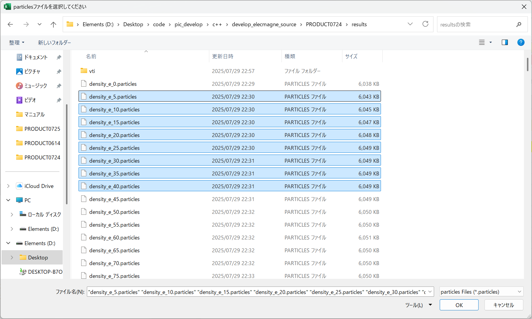
⑤Open the output destination for the calculation results (the folder selected in step 6), select one .particles file, and click the OK button. If you want to view the entire animation of the calculation results, select multiple .particles files and click the OK button. When multiple files are selected, they will automatically be renamed to density_e_*.particles, etc.
Note that density_e_*.particles represents electron density, density_i_*.particles represents ion density, and density_n_*.particles represents neutral particle (gas) density.
ⅰ)Visualization of one frame of calculation results
ⅱ)Visualize the entire calculation result with animation
⑥After completing other inputs, select the 『Visualization』 button to automatically launch the command prompt and start visualization.
例)magnetron sputtering