What Is Plasma?
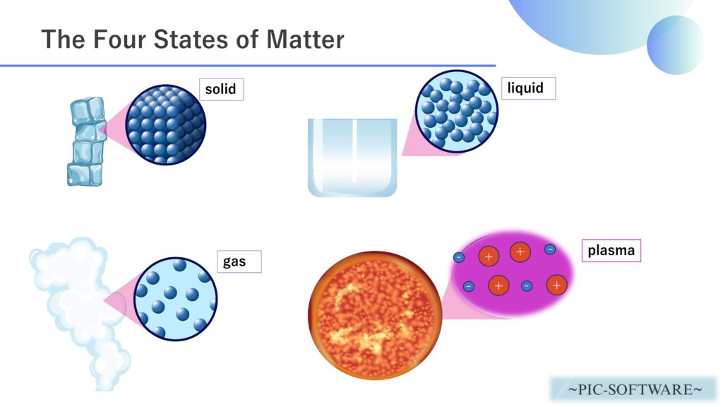
Figure 1: Four States of Matter
Matter is commonly classified into solids, liquids, and gases, but by heating a gas further, it is possible to generate plasma.
For this reason, plasma is often referred to as the “fourth state of matter.”


In this article, we will analyze an industrial plasma cutting machine using PIC-PLASMA 3D (plasma analysis software).
A plasma cutting machine cuts metal by turning gas into plasma using electrical energy, then melting and blowing away the metal with an ultra-high-temperature, high-speed jet.
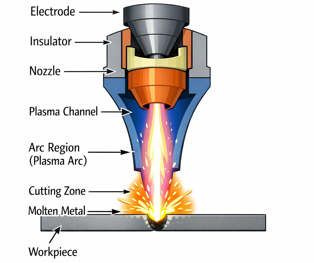
Figure 2: Conceptual Diagram of a Plasma Cutting Machine
The basic principle is as follows:
-
- Gas supply
- Arc generation
- Ionization of gas into plasma
- Melting of metal by the plasma jet
- Removal of molten metal
- Cutting
Plasma cutting is used for conductive materials such as iron, stainless steel, and aluminum. Gas such as compressed air or nitrogen is fed through a narrow nozzle while an arc is generated between the electrode inside the torch and the workpiece.
This arc ionizes the gas, creating a high-temperature conductive plasma flow that not only “melts” the metal but also “blows it away,” thereby achieving cutting.
Inside the equipment, a self-bias voltage is generated by applying high frequency to the electrode that holds the substrate, making it easier for ions to strike the substrate almost vertically. As a result, fine patterns can be processed deeply and accurately without widening sideways.
The features of a plasma etching system are:
- Can cut metal quickly
- Suitable for medium-thickness plates
- Relatively high precision
- Highly versatile equipment
These are its main advantages.
On the other hand,
- Heat effects and consumable part management are required
These are some of the challenges.
In short, a plasma etching system is a device that precisely removes material from a surface by utilizing the chemical reactivity and ion bombardment of plasma generated in a vacuum.
Load Analysis on the Target in a Plasma Cutting Machine
Let’s perform a collision simulation on the target in a plasma cutting machine using PIC PLASMA 3D.
The analysis model is shown below.
Analysis Model
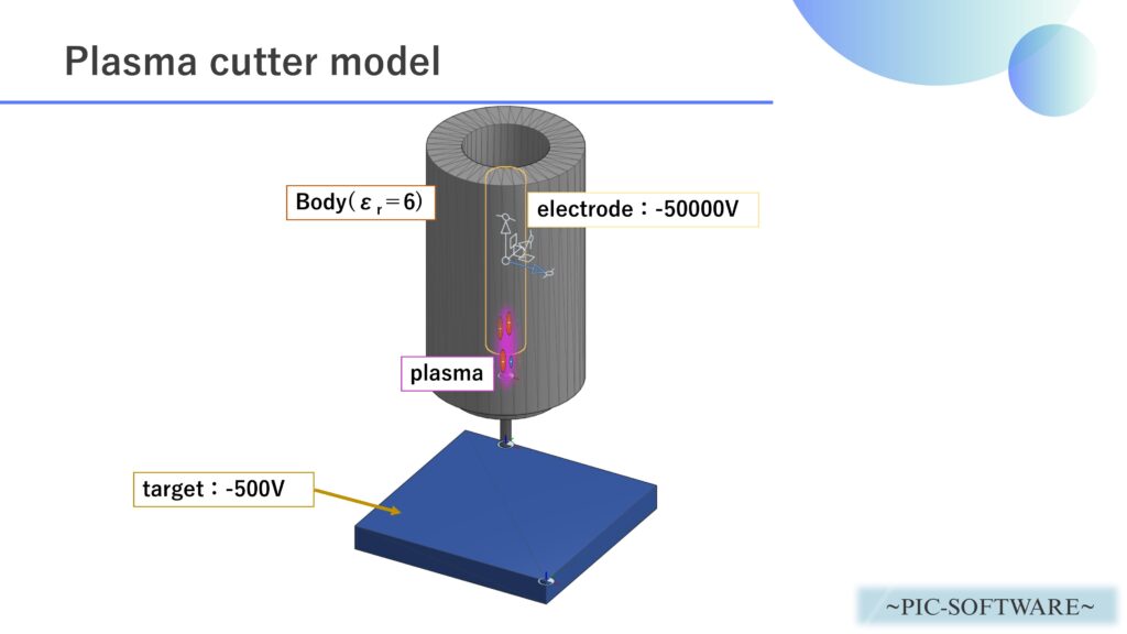
Figure 3: Analysis Model of the Plasma Etching System
A plasma cutting machine model like the one above was created, and plasma trajectory analysis and collision simulation on the target were carried out.
The plasma generation mechanism is shown below.
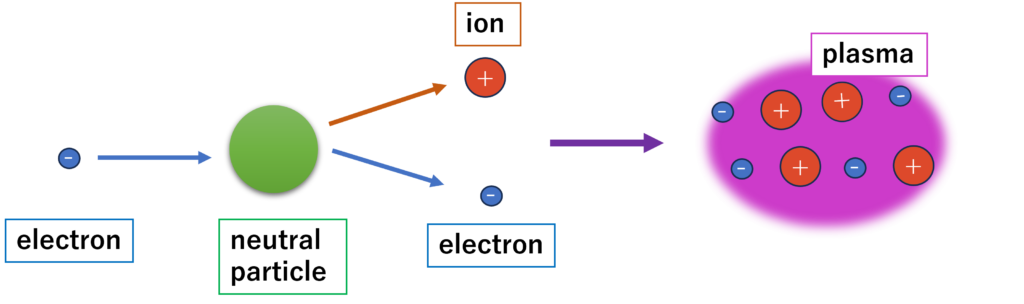
Figure 4: Plasma Generation Process
Analysis Conditions
The analysis conditions are as follows.
| Analysis Software | PIC-PLASMA 3D |
| Analysis Type | Plasma Analysis |
| Analysis Object | plasmacutting.obj |
|---|---|
| Plasma Particle Species | O₂ |
| Plasma Density | 1.0×10¹¹ [particles/m3] |
| Cumulative Energy Target Object | target |
| Voltage | target: -500 [V] , arc: 0 [V] , electrode: 500 [V] |
| Time Step | 1.0×10⁻⁹ [s] |
| Total Simulation Time | 2.0×10⁻⁶ [s] |
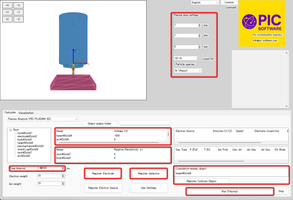
Figure 5: Setting Analysis Conditions in PIC-PLASMA 3D
Analysis Results
Figure 6: Plasma Ion Trajectory Analysis in the Plasma Cutting Machine
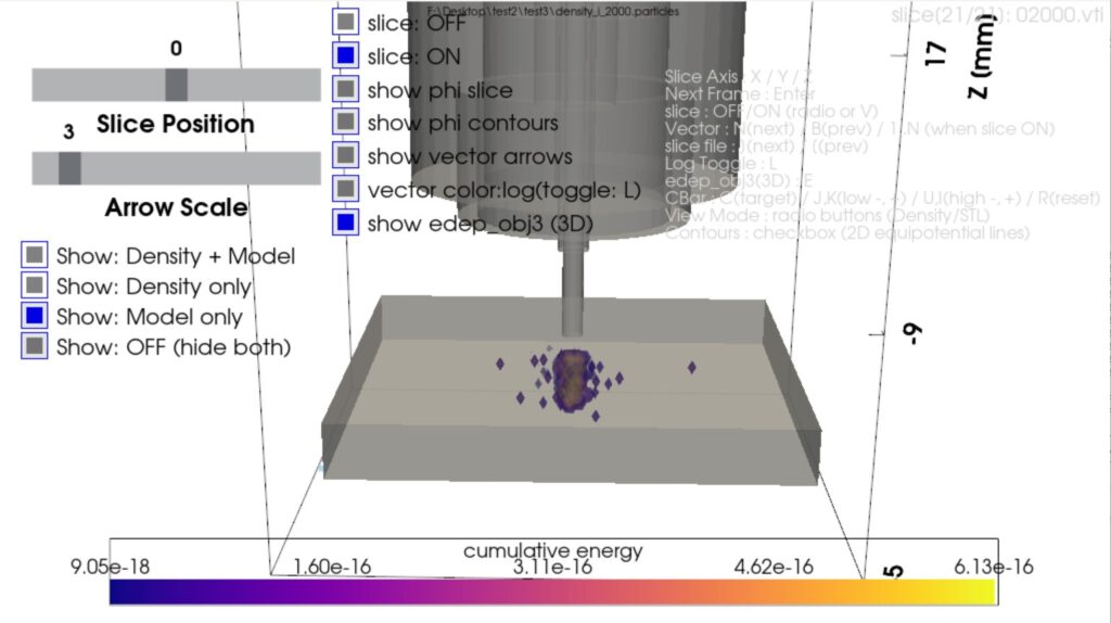
Figure 7: Cumulative Plasma Collision Energy on the Target
The materials above are actual analysis results calculated using PIC-PLASMA3D.
Figure 6 visualizes the behavior of ions (O₂+) in the plasma as an animation. Figure 7 shows the cumulative collision energy (kinetic energy) between the target and the plasma.
Please note that the CAD model used here was created in a simplified manner, so the electrode voltages and other conditions are also simplified.
In addition to the calculation results shown above, PIC-PLASMA 3D can output a variety of other data.
- Electron density
- Current density vectors
- Electric field vectors
- Velocity vectors
- Collisions between plasma and background gas or jet gas
*The above are just examples. Please make full use of PIC-PLASMA 3D for the development of plasma-related products.