Electron Trajectories Inside an SEM
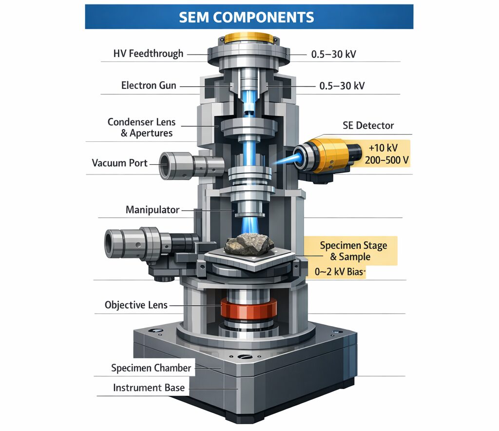
Figure 1: Conceptual illustration of electron trajectories in an SEM
What is an SEM? In an SEM, electrons emitted from the electron source are accelerated and shaped into a narrow beam by electromagnetic lenses and apertures before being directed onto the sample. By detecting secondary electrons and backscattered electrons generated at the sample surface, differences in surface morphology and composition can be observed.-
-
- Electron Emission Electrons are emitted from the electron source (cathode).
- Electron Acceleration Kinetic energy is given to the electrons by the anode voltage.
- Electron Beam Focusing The electron beam is focused by electromagnetic lenses or electrostatic lenses.
- Sample Irradiation The focused electron beam is directed onto the sample surface.
- Signal Detection Secondary electrons and backscattered electrons are detected to form an image.
-
E = eV
・e: electron charge
・V: voltage
SEM Analysis
Let us analyze electron trajectories inside an SEM using PIC-ELECTRON 3D. The analysis model is shown below. Analysis Model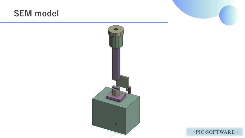
Figure 2: SEM analysis model
We create a simplified analysis model of the SEM interior as shown above and simulate the process from electron beam generation to arrival at the sample. The role of each component in the SEM is as follows.-
-
-
- Electron Source The part that emits electrons. It is a key factor that determines beam quality in the SEM.
- Wehnelt Electrode An electrode that controls the extraction amount of electrons and the initial focusing condition. It helps form the electron beam.
- Anode An electrode that accelerates electrons and sends them downstream. It is the central part that provides the accelerating voltage.
- Electromagnetic Lens A lens used to focus the electron beam more tightly. It greatly affects the focal position and beam diameter.
- Aperture A component that limits the range of passing electrons and suppresses unnecessary beam spreading.
- Sample The observation target irradiated by the electron beam. Secondary electrons and backscattered electrons are generated here.
- Vacuum Chamber A space that maintains a vacuum so electrons do not collide with air molecules.
- Insulator A component that electrically insulates each electrode and structure while maintaining positional relationships.
-
-
| Analysis Software | PIC-ELECTRON 3D |
| Analysis Type | Electron Trajectory Analysis |
| Analysis Object | sem.obj |
| Voltage | Cathode: -3000 [V] Anode: 0 [V] Sample: 0 [V] |
| Relative Permittivity (Dielectric) | Insulator: 9.5 |
| Magnetic Field Condition | Electromagnetic Lens: Set according to the analysis conditions |
| Number of Generated Electrons per 1 ns | 10,000 |
| Initial Velocity of Generated Electrons | 1.0×10³ [m/s] |
| Time Step | 1.0×10⁻¹¹ [s] |
| Total Simulation Time | 2.0×10⁻⁸ [s] |

These initial conditions can be set directly in the software (PIC-ELECTRON 3D).
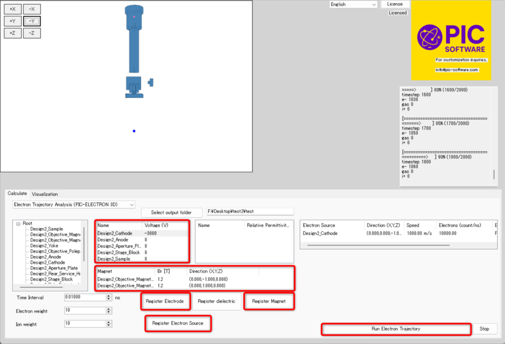
Figure 3: SEM analysis condition settings in PIC-ELECTRON 3D
Analysis Results
Figure 4: Electron trajectory analysis inside an SEM
The material above is an example of electron trajectory analysis results inside an SEM actually calculated using PIC-ELECTRON 3D. In Figure 4, you can see electrons emitted from the electron source being transported toward the sample while being focused more narrowly by the accelerating voltage and lens action. In an SEM, the divergence and convergence state of the electron beam affects observation resolution, so this kind of electron trajectory analysis is useful for equipment design and condition optimization. Please note that the CAD model used here was created as a simplified model, so the lens conditions and component shapes are simplified for explanatory purposes. In addition to the calculation results shown above, PIC-ELECTRON 3D can also output various kinds of data.- Electron density
- Current density vectors
- Electric field vectors
- Magnetic field vectors
- Velocity vectors
- Arrival energy distribution