What is Plasma?

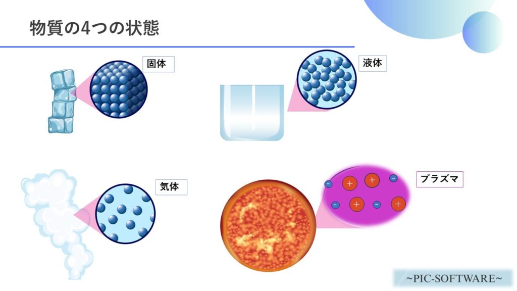
Matter is often divided into solid, liquid, and gas, but plasma can be created by further heating gas.
For this reason, plasma is often described as the “fourth state” of matter.
Plasma is the ionized state of matter.
Ionization is a phenomenon in which a molecule or atom breaks apart and separates into electrons and ions.


In this article, we will analyze magnetron sputtering equipment, an industrial product that uses plasma.
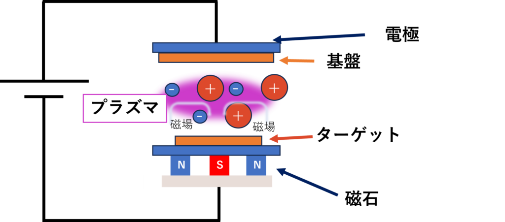
A magnet that generates a magnetic field is placed behind the target to confine electrons within the magnetic field, producing a high-density plasma.
This increases the frequency with which ions strike the target compared to a two-pole sputtering system, thereby increasing the deposition rate.
Magnetron sputtering equipment is,
- Semiconductor manufacturing
- Display manufacturing
- Medical equipment
- Electronic component manufacturing
- Optical component manufacturing
It is used in various research and industrial fields such as those listed above.

Fig.1: Conceptual diagram of magnetron sputtering equipment
The figure above shows a conceptual diagram of the magnetron sputtering system.
The deposition process of magnetron sputtering equipment is as follows
- Electrons are emitted from the cathode.
- Electrons are trapped around the target by a magnet.
- The trapped electrons collide with the gas near the target, generating plasma.
- Ions in the generated plasma are attracted to the cathode and collide with the target.
- Target atoms are ejected, deposited on the substrate, and deposited.
Analysis of magnetron sputtering equipment
Use our PIC PLASMA3D to simulate plasma in magnetron sputtering equipment.
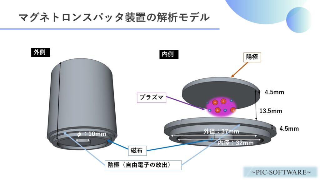
The analytical model is as follows (Created with FreeCAD)
Analysis Model

We created an analytical model for magnetron sputtering as described above and performed orbital analysis of free electrons (particles that are the origin of plasma generation) emitted from the cathode.
In the case of this magnetron sputtering system, electrons emitted from the cathode are affected by the magnetic field, and electrons are trapped around the cathode.

Therefore, it can achieve more efficient sputtering than electrode-only sputtering equipment.
The mechanism of plasma generation is as follows.

図2:プラズマの生成過程


Analysis conditions
The analysis conditions are as follows
| Analysis Software | PIC PLASMA3D(lite) or PIC PLASMA3D(pro) |
|---|---|
| Analysis type | Orbital analysis of plasma in electrostatic and static magnetic fields |
| Initial electron density | 1.0×10¹¹[pcs/m3] |
| Newly generated particles | electron |
| Initial velocity of generated electrons | 70[m/s] |
| Average density of generated electrons | 1.0×10¹⁷[pcs/m3] |
| Voltage | Cathode voltage:0[V] Anode voltage:400[V] |
| residual flux density | Cylinder magnet:1.2[T] (upward) Ring magnet:1.2[T] (downward) |
| time step width | 1.0×10⁻¹¹[s] |
| Total simulation time | 1.0×10⁻⁸[s] |


Analysis Results
図3:陰極から放出される自由電子の解析結果
The above video is a visualization of the actual results calculated by PIC-PLASMA3D (regular version).
We simulate the trajectories of free electrons emitted from the cathode, which is the origin of plasma generation.
The “data” in the movie indicates the number density of electrons [pcs/m3].


Since the cad model used in this study was created in a simplified manner, the number of electrons and other condition settings have been simplified.
In addition to the above calculation results, PIC-PLASMA3D can also output various data.
- Electrostatic potential
- Magnetic field distribution
- Electron density
- Current density
- Charge density
※The above is an example.
We hope you will utilize the PIC-PLASMA3D, which we have analyzed in this study, to improve the performance of your plasma products.