What Is Plasma CVD?
In thin-film formation, it is important to deposit materials uniformly on a substrate. Plasma CVD is a method of forming thin films by activating source gases with plasma and causing chemical reactions on the substrate surface.
Compared with conventional CVD, which relies mainly on heat to drive reactions, plasma CVD can promote reactions even at relatively low temperatures. For this reason, it is widely used for forming semiconductor films, insulating films, and protective coatings.


In this article, we will use PIC-PLASMA 3D (plasma analysis software) to analyze plasma distribution inside an industrial plasma CVD reactor and the tendency of particles to reach the vicinity of the substrate.
Basic Principle of a Plasma CVD System
A plasma CVD system is a device that activates reactive gases by plasma and grows a thin film on the substrate surface. For example, source gases such as SiH4, NH3, and O2 are introduced and discharged by RF power to generate ions, electrons, and radicals.
The basic principle is as follows:
- Introduce source gas and dilution gas into the vacuum chamber
- Apply high-frequency power between the upper electrode or showerhead and the lower stage
- Electrons collide with gas molecules, causing ionization, excitation, and dissociation to form plasma
- The generated radicals and ions are transported toward the substrate
- Adsorption, reaction, and recombination occur on the substrate surface, forming a thin film
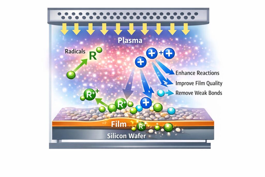
Role of radicals: Neutral radicals generated in the plasma play a major role in chemical reactions on the substrate surface. They act as precursors required for film formation and affect film composition and deposition rate.
Role of ions: Ions are accelerated by the sheath electric field near the substrate and reach the surface. Excessively strong ion bombardment can lead to film damage and increased defects, while moderate ion assistance can improve film quality and densification.
In other words, in plasma CVD it is important to properly control both radical transport, which drives chemical reactions, and ion incidence, which affects the surface condition.
What to Observe in Plasma CVD Analysis
In plasma CVD systems, not only deposition rate but also film thickness distribution, film quality, substrate damage, and reaction uniformity inside the reactor are important. Therefore, it is valuable to understand the following points through simulation:
- Plasma density distribution inside the chamber
- Potential and electric field distribution above the substrate
- Ion arrival direction and energy trends
- Bias in particle transport from the gas inlet to the substrate
- Spatial distributions affecting deposition uniformity
In particular, if a thin film is to be formed uniformly across the entire substrate, the balance among the discharge region spread, showerhead geometry, stage position, and chamber dimensions becomes important.
Analysis of Plasma Distribution Inside a Plasma CVD Reactor
Let us use PIC-PLASMA 3D to examine the discharge region inside a plasma CVD reactor and the trend of particle transport toward the substrate vicinity.
Analysis Model
In this analysis, a simplified plasma CVD reactor model was used, featuring a showerhead electrode in the upper part that also serves as the gas introduction mechanism, and a substrate stage in the lower part. Rather than detailed manufacturing CAD, priority was given to an analysis-oriented model that makes it easier to understand the plasma generation region, sheath formation region, and substrate vicinity region.
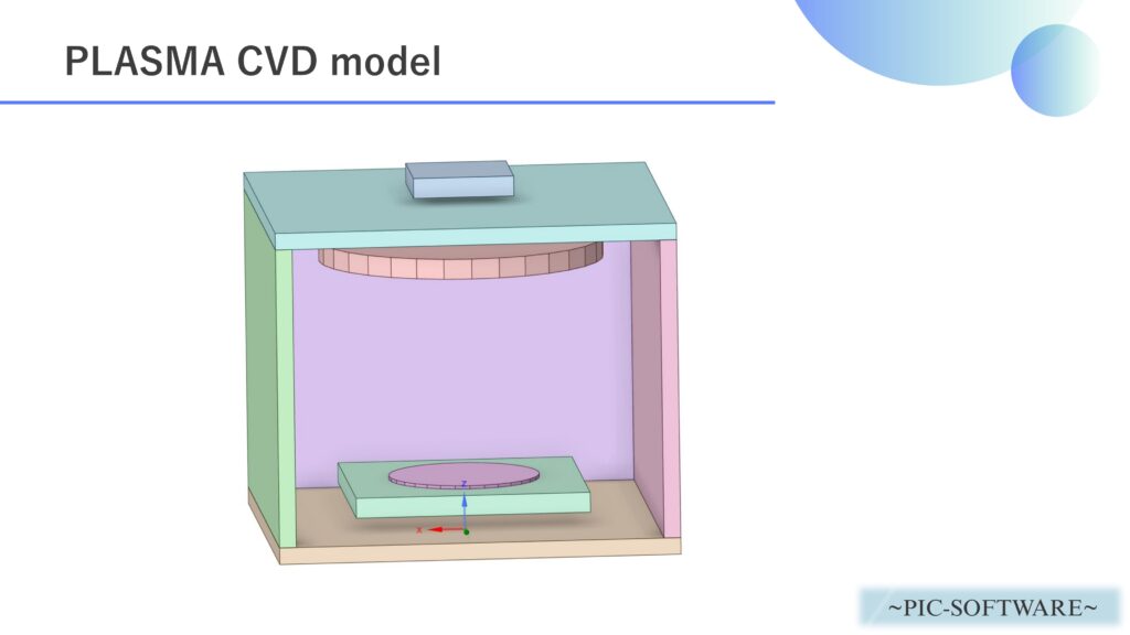
Figure 1: Analysis model of a plasma CVD reactor
In the model, source gas supplied from the gas inlet is assumed to discharge in the upper region, and the generated ions, electrons, and radicals are transported toward the substrate.
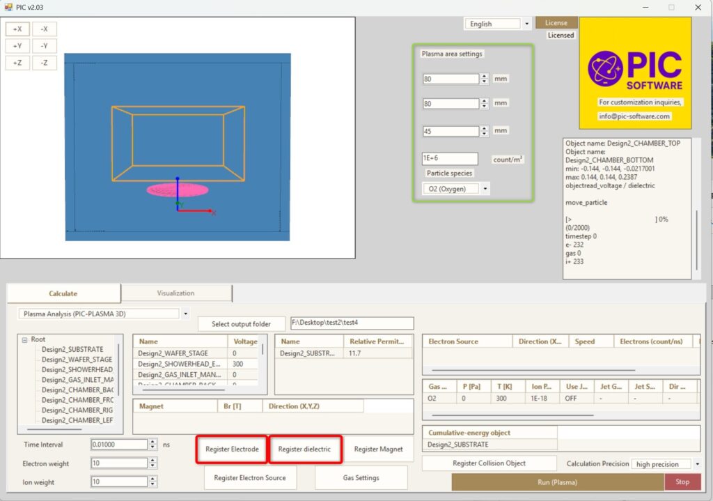
Analysis Conditions
The analysis conditions are as follows.
| Analysis Software | PIC-PLASMA 3D |
| Analysis Type | Plasma Analysis |
| Analysis Object | plasma_cvd_reactor.obj |
| Target Process | Plasma CVD |
| Representative Gas Species | O2 |
| Plasma Density | 1.0×10⁶ [/m3] |
| Applied Condition | Potential difference condition simulating RF application to the upper electrode |
| Time Step | 1.0×10⁻⁸ [s] |
| Total Simulation Time | 2.0×10⁻⁵ [s] |
| Focus Items | Plasma distribution, electric field distribution, and particle arrival tendency near the substrate |
In actual deposition, detailed modeling of gas reactions and surface reactions is also important, but in this model the focus is first placed on understanding the discharge structure and particle transport tendency inside the reactor.
Analysis Results
As one example of the analysis results, it can be confirmed that inside the chamber, a discharge region is formed from the vicinity of the upper showerhead down to the area above the substrate, securing a relatively wide plasma generation space between the electrodes.
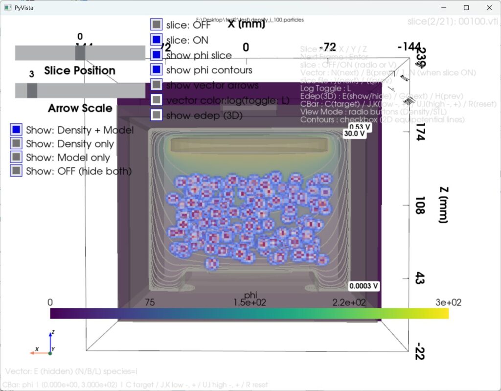
Figure 2: Ion density and electric field inside the plasma CVD reactor
Near the substrate, the electric field becomes stronger due to sheath formation, making it easier for ions to be transported toward the substrate. On the other hand, at the chamber edges, bias in electric field distribution and particle density tends to occur, which may affect film thickness uniformity.
Figure 3: Behavior of plasma ions and electric field distribution
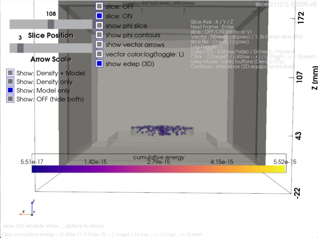
Figure 4: Cumulative particle impact energy on the target
Such analysis can lead to the following design studies:
- Review of showerhead position and opening distribution
- Optimization of stage height and electrode spacing
- Study of the balance between chamber dimensions and discharge space
- Improvement of deposition uniformity across the substrate
- Reduction of film damage by suppressing excessive ion bombardment
This model is a simplified CAD model for analysis, so it omits details such as the actual gas flow path, RF power feed section, and detailed surface reactions. However, by using PIC-PLASMA 3D, it is possible to examine in advance how reactor geometry affects plasma distribution and particle behavior near the substrate.
Summary
Plasma CVD is an important process capable of forming high-performance thin films at relatively low temperatures by using reactive species and ions generated in plasma. At the same time, deposition uniformity and film quality are greatly influenced by the plasma distribution inside the reactor and the electric field structure near the substrate.
By using PIC-PLASMA 3D, you can visualize the discharge region, particle transport, and electric field distribution inside a plasma CVD reactor, helping with equipment design and condition optimization.
- Confirmation of plasma density spatial distribution
- Visualization of electric field vectors
- Confirmation of particle trajectories
- Evaluation of arrival tendency near the substrate
- Comparative study when changing reactor geometry
Please consider using PIC-PLASMA 3D for initial design of plasma CVD systems and for studying deposition conditions.